Call us now: +1(800) 123 4567
Email: oesus@support.com

Industrial electrical faults are not always easy to identify. A motor drive may produce unexpected voltage spikes, a control circuit may experience intermittent noise, or a switching power supply may behave differently under load. Yet, when technicians inspect these systems with an oscilloscope that has insufficient bandwidth, important waveform details can disappear from the display.
Choosing a Fluke oscilloscope for industrial signals therefore involves more than comparing model numbers. Engineers need to understand the frequency content of the signals they measure, the speed of waveform transitions, and the level of detail required for reliable troubleshooting.
The right bandwidth helps technicians observe electrical behavior more accurately, investigate faults efficiently, and make better maintenance decisions. However, selecting the highest available bandwidth does not automatically produce the best result for every application. The goal is to match the instrument to the measurement task.
Oscilloscope bandwidth describes the frequency response of the instrument’s input system. Manufacturers generally specify it at the frequency where a sine wave’s displayed amplitude falls to approximately 70.7% of its original value, also known as the −3 dB point.
This specification matters because an oscilloscope cannot reproduce every frequency component with equal accuracy. As signal frequency approaches the instrument’s bandwidth limit, the displayed amplitude may decrease. Fast transitions and complex waveforms can also lose important details.
For industrial technicians, bandwidth affects the ability to examine:
Consider a technician investigating an inverter that occasionally triggers a fault. A basic meter may report an acceptable average voltage, while an oscilloscope reveals brief spikes during switching. If the instrument cannot reproduce the relevant frequency components, those spikes may appear smaller or less defined than they actually are.
Therefore, oscilloscope bandwidth should match the characteristics of the signal under test, not simply its nominal operating frequency.
The most useful starting point is to identify the fastest or most demanding signal you need to examine. A stable sine wave and a fast switching pulse can require very different measurement capabilities, even when their fundamental frequencies appear similar.
For a relatively clean sine wave, an oscilloscope with bandwidth comfortably above the signal frequency can usually provide a useful amplitude measurement. However, distorted signals contain additional frequency components called harmonics.
A common engineering rule of thumb is to choose bandwidth at least five times the highest fundamental or clock frequency when preserving waveform shape is important. This is a practical starting point rather than a universal guarantee of accuracy.
For example, suppose an industrial controller produces a 10 MHz clock signal. A 50 MHz oscilloscope may be a reasonable initial candidate for inspecting its general waveform shape. If the task involves measuring very fast edges, overshoot, or subtle ringing, the technician must also evaluate rise time, sampling rate, probes, and the required measurement accuracy.
Fast voltage transitions contain high-frequency components beyond the fundamental repetition frequency. Consequently, a low-frequency pulse can still require substantial bandwidth if its rising and falling edges are extremely fast.
For an oscilloscope with a typical Gaussian-like response, engineers often estimate instrument rise time using:
Oscilloscope rise time ≈ 0.35 ÷ bandwidth
Use consistent units. For example, a 100 MHz instrument has an estimated rise time of approximately 3.5 nanoseconds. A 200 MHz instrument has an estimated rise time of approximately 1.75 nanoseconds.
A useful rule of thumb is to choose an oscilloscope rise time no greater than one-fifth of the fastest rise time you need to measure. Actual performance depends on the instrument’s response, probe characteristics, and measurement setup.
Fluke explains this relationship in its technical article on oscilloscope bandwidth and waveform rise time.
Different industrial applications place different demands on an oscilloscope. A technician should define the diagnostic objective before selecting a bandwidth range.
Variable-frequency drives and inverters switch semiconductor devices to control motor speed and torque. Their waveforms can include steep transitions, overshoot, ringing, and switching noise.
When troubleshooting these systems, engineers should consider the switching behavior and the fastest edge they need to capture. A bandwidth that works for observing slower control signals may not reveal the same detail in a fast switching event.
In addition, use suitable probes and follow the instrument’s voltage and measurement-category ratings. High-energy electrical systems require particular attention to safe connection methods.
Programmable logic controllers and digital control circuits use signals that may appear simple at first glance. However, timing faults, short pulses, and electrical interference can cause intermittent operational problems.
For these applications, choose bandwidth based on the fastest transitions and shortest events that matter to the diagnosis. Sampling rate and acquisition memory also influence whether the oscilloscope can capture the event with sufficient detail.
Switch-mode power supplies contain switching waveforms, ripple, and transient behavior. Engineers may need to inspect switching frequency, startup behavior, load changes, and unexpected oscillations.
A suitable oscilloscope must capture the relevant waveform details without overlooking short-duration events. Probe bandwidth, grounding, and measurement technique can significantly affect the result, especially when examining high-frequency switching nodes.
For slower electrical signals, control voltages, and many routine maintenance tasks, an extremely high bandwidth may provide little practical benefit. Instead, usability, measurement functions, portability, channel count, and safety ratings may matter more.
The best choice is the instrument that captures the information required for the actual job.
Even when bandwidth looks suitable on paper, other specifications can limit the quality of a measurement. Evaluate the complete measurement system rather than choosing an instrument based on one number.
Sampling rate describes how frequently the oscilloscope converts the input signal into digital samples. A higher rate can provide more time-domain detail, but it does not compensate for inadequate analog bandwidth.
Check the maximum sampling rate for the number of channels you intend to use simultaneously. Some instruments reduce the available sampling rate when additional channels are active.
Memory depth determines how many samples the instrument can retain for a captured record. Deep memory helps when technicians need to examine a short transient while preserving a longer time window around the event.
For intermittent industrial faults, look for useful acquisition features such as single-shot capture, waveform recording, trigger options, and replay. These functions help investigate events that do not occur consistently.
A probe can limit the effective bandwidth of the entire measurement chain. Its attenuation, bandwidth, loading, and connection method all influence the waveform that reaches the oscilloscope.
Safety is equally important. Before connecting an instrument to a drive, panel, or power circuit, verify the instrument’s voltage limits, measurement-category rating, probe rating, and operating instructions. Never assume that a high-bandwidth instrument is automatically suitable for high-energy measurements.
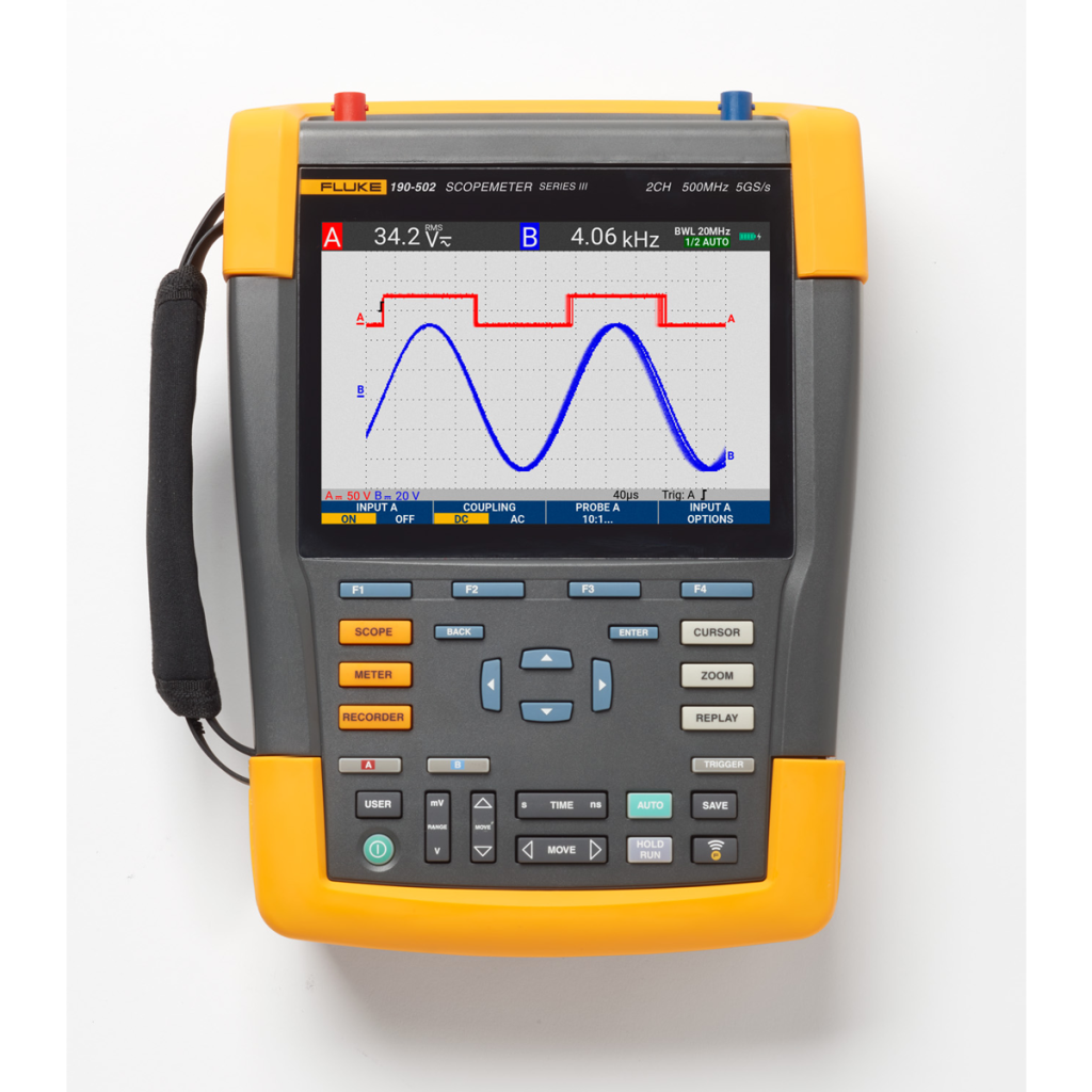
A Fluke oscilloscope can be useful when technicians need to inspect waveforms directly at industrial equipment rather than move the system under test to a laboratory. Portable instruments can combine waveform analysis with features designed for field troubleshooting.
When comparing models, focus on the requirements of your maintenance team.
For example, a maintenance team that primarily checks slower control signals may prioritize ease of use and suitable safety ratings over very high bandwidth. By contrast, a team investigating fast switching behavior may need greater bandwidth, faster rise time, and higher sampling performance.
Compare specifications against your real measurement tasks rather than assuming one model will suit every application. You can review available equipment and related product information through the TRUEPOINTLAB shop.
Before purchasing or assigning an oscilloscope to a job, answer these questions:
These questions help turn a broad specification comparison into a practical selection process. They also reduce the risk of paying for capabilities that your team rarely uses—or choosing an instrument that cannot reveal the fault you need to diagnose.
For additional information about measurement equipment and technical solutions, visit the TRUEPOINTLAB website.
Choose bandwidth according to the highest relevant signal frequency and the fastest edge you need to measure. For waveform-shape analysis, five times the fundamental frequency is a common starting point, but fast transitions may require a different calculation.
No. Higher bandwidth can preserve more high-frequency detail, but it may add cost without improving routine measurements. Select a model that meets your signal, accuracy, safety, and recording requirements.
Rise time indicates how quickly an oscilloscope can respond to a signal transition. If the instrument responds too slowly, it may display fast edges as slower than they really are and obscure details such as overshoot or ringing.
Neither specification works in isolation. Bandwidth determines the analog frequency response, while sampling rate determines how frequently the signal is digitized. Both must suit the measurement, along with memory depth and probe performance.
Verify the bandwidth, rise time, probes, voltage limits, and measurement-category ratings. Also check isolation, channel configuration, and the instrument’s instructions before connecting to potentially hazardous circuits.
The right oscilloscope bandwidth helps industrial technicians see the signal details that matter without overcomplicating equipment selection. By evaluating signal frequency, edge speed, sampling performance, probes, and safety requirements together, engineers can make a more informed choice for field diagnostics and maintenance. TRUEPOINTLAB provides a starting point for exploring measurement equipment and identifying options that fit your technical requirements.
TruePointLab.© 2026. All right reserved