Call us now: +1(800) 123 4567
Email: oesus@support.com

An industrial machine runs normally for hours, then suddenly stops. The control panel shows no obvious error, voltage readings appear acceptable, and restarting the equipment temporarily resolves the problem. By the time a technician arrives with a conventional multimeter, the fault has disappeared.
This situation is common when electrical problems occur intermittently. Loose connections, electrical noise, voltage dips, failing components, and switching transients can disrupt equipment without producing a continuous symptom. To identify the real cause, technicians need to capture the electrical event while it happens.
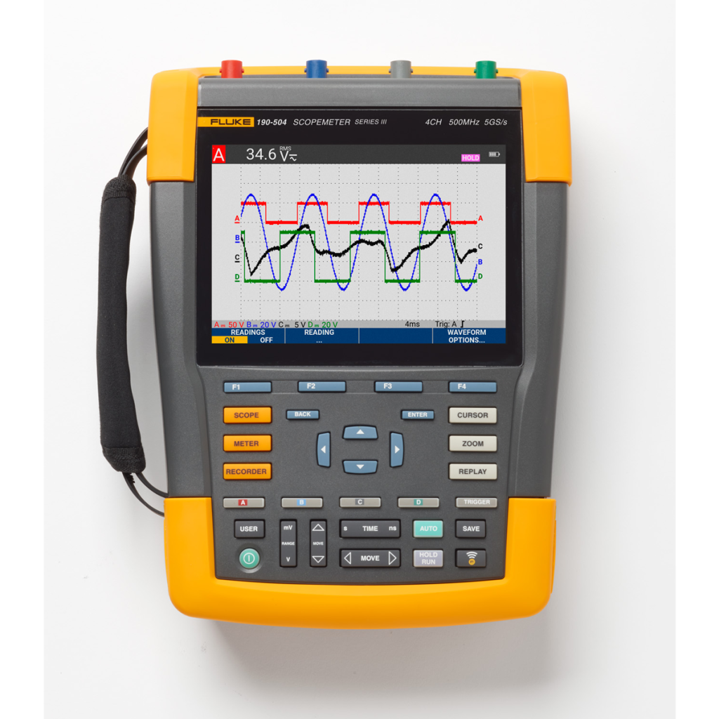
A Fluke oscilloscope helps maintenance professionals observe voltage changes over time, investigate unusual waveforms, and record events for later analysis. However, successful troubleshooting depends on more than connecting probes. Technicians must configure the trigger, choose the appropriate acquisition mode, and preserve enough waveform information to understand what happened before the failure.
An intermittent electrical fault occurs when a circuit behaves abnormally for a limited period and then returns to normal. Because the event may last only microseconds, milliseconds, or several seconds, a technician can easily miss it during a routine inspection.
Common causes include:
For example, a production line may stop whenever a contactor operates. A standard voltage measurement taken afterward might show a normal supply. However, a captured waveform could reveal a brief voltage interruption or a disturbance in the control circuit.
The objective is to capture the event, not merely measure the circuit after the event has passed.
A digital oscilloscope supports this process by displaying signal amplitude against time. Depending on its capabilities, it can also retain previous waveform screens, record signal behavior over extended periods, and trigger automatically when a defined condition occurs.
When a problem happens unpredictably, technicians should prepare the instrument before returning the machine to service. A suitable initial setup increases the likelihood of capturing useful evidence.
Start by reviewing the equipment’s electrical diagram and maintenance history. Determine which signal is most likely to reveal the problem.
For instance, if a motor stops unexpectedly, possible measurement points include the control signal, supply voltage, drive output, or another relevant signal identified by the equipment manufacturer. Monitoring the right point is essential because a waveform from an unrelated circuit may not explain the failure.
Adjust the vertical scale in volts per division so the expected signal fits clearly on the display. Avoid settings that clip the waveform or make small disturbances difficult to distinguish.
Next, select a time base that captures the event’s expected duration. A short time window provides detail about fast transitions, while a longer window reveals the sequence leading up to a shutdown.
When the event duration is unknown, consider an acquisition or recording mode that preserves a longer history and allows later zooming.
The instrument needs enough bandwidth to reproduce the signal features relevant to the investigation. Sampling rate and memory depth also influence the detail and duration of a captured waveform.
Review these specifications alongside the probe’s bandwidth, attenuation, and electrical ratings. For further guidance, see the TRUEPOINTLAB article on choosing Fluke oscilloscope bandwidth for industrial signals.
Triggering tells the oscilloscope when to acquire or display a waveform. Instead of watching a constantly changing screen, technicians can configure the instrument to respond to a particular electrical condition.
Edge triggering detects a signal crossing a specified voltage level in a rising or falling direction. It provides a practical starting point when investigating sudden voltage changes.
Suppose a control signal normally remains near 24 V DC but occasionally drops sharply. A technician can configure a falling-edge trigger at a suitable threshold below the normal operating level. When the signal crosses that threshold, the oscilloscope can capture the event.
The threshold should reflect the circuit’s normal behavior and the fault being investigated. Setting it too close to the normal signal level may produce unnecessary captures from ordinary fluctuations.
Some faults involve pulses that are too short, too long, or irregular. Pulse-width triggering can help identify these conditions when the oscilloscope supports the required trigger mode.
For example, a controller may generate pulses with a consistent duration during normal operation. A pulse-width trigger can help isolate an unusually short pulse that may indicate interference or a control-system problem.
Single-shot mode waits for a defined trigger condition and captures the event when it occurs. This approach works well for infrequent events such as a relay transition, an unexpected shutdown, or a momentary disturbance.
However, the instrument must remain armed, and the trigger settings must match the event. If the threshold or pulse condition does not reflect the fault, the oscilloscope may never trigger.
For a deeper explanation of capture methods, consult Fluke’s portable oscilloscope product information.
Triggering works best when technicians can describe the abnormal condition. Sometimes, however, the fault is too unpredictable to define a precise trigger in advance. In these cases, waveform recording and historical capture become especially useful.
Some portable oscilloscopes retain a rolling sequence of recent screen captures. When an anomaly appears, technicians can stop the acquisition and review the preceding screens.
This approach helps establish whether the disturbance started before the machine stopped, occurred during switching, or appeared after another electrical change.
A recording mode can preserve waveform samples over a longer interval than a conventional screen capture. Technicians can then inspect the recorded data and zoom in on specific events.
For example, a machine may trip once every few hours. A recording feature can help preserve the voltage behavior around the trip, depending on the instrument’s memory, sampling settings, and recording mode.
Not every intermittent fault involves a fast transient. Some problems develop gradually through voltage drift, fluctuating current, or changing signal levels.
Trend-recording functions help technicians identify these patterns across longer periods. They can reveal whether the fault correlates with a changing load, equipment startup, or another operating condition.
Choose the acquisition method according to the event:
The available functions vary by model, so confirm the recording duration, sample resolution, trigger options, and memory capacity before relying on a particular method.
Capturing an abnormal waveform is only the first step. The next task is to determine whether the event explains the equipment failure.
Begin by comparing the captured waveform with a known-good signal or the expected operating specification. Look for differences in amplitude, timing, pulse width, frequency, or transition shape.
For example, a control signal that normally remains stable may show a brief drop immediately before a machine stops. That observation provides a useful lead, but it does not automatically prove the signal drop caused the shutdown.
Use the waveform’s time axis and any available timestamps to establish the order of events. Did the voltage disturbance occur before the controller reset? Did the current increase before the protective device tripped? Did the control signal disappear before the contactor released?
This sequence helps technicians distinguish a possible cause from a secondary symptom.
Repeat the measurement under comparable operating conditions when safe and practical. Check related test points and compare the results with equipment documentation.
A useful troubleshooting record should include:
This documentation makes the diagnosis easier to review and helps maintenance teams determine whether the problem has genuinely been resolved.
The best instrument depends on the electrical environment, signal characteristics, and duration of the fault. Before selecting a Fluke oscilloscope, check whether its features match the task rather than focusing on a single specification.
Prioritize these capabilities:
Safety requires equal attention. Before connecting a probe, verify the instrument’s measurement-category rating, maximum input voltage, probe rating, and the requirements of the circuit under test. Use accessories designed for the application and follow the manufacturer’s instructions.
Never assume that a probe’s voltage rating alone establishes its suitability for a high-energy circuit. Measurement category, transient exposure, connection method, and instrument isolation all matter. De-energize equipment when required by the applicable procedure, and allow qualified personnel to perform measurements on hazardous electrical systems.
For industrial maintenance teams, a well-configured portable oscilloscope can turn an elusive symptom into measurable evidence. Explore the measurement equipment information available on the TRUEPOINTLAB website to help identify tools suited to your application.
Yes. Depending on the model, triggering, waveform replay, and recording functions can capture or preserve unusual electrical events for later analysis.
Use edge triggering for voltage transitions, pulse-width triggering for abnormal pulse durations, and single-shot capture for isolated events. Choose the mode that matches the expected fault.
Use a suitable recording or historical capture function and configure the instrument before returning the equipment to service. Check memory capacity and recording duration to ensure the event can be preserved.
Possible causes include an unsuitable trigger threshold, incorrect time base, insufficient acquisition duration, limited bandwidth, or monitoring the wrong test point. Review the setup and confirm that the trigger condition matches the suspected fault.
An oscilloscope shows how a signal changes over time, making it useful for brief transients and waveform abnormalities. A multimeter remains valuable for routine voltage, resistance, and continuity checks. The two instruments serve complementary purposes.
Capturing intermittent electrical faults requires preparation, appropriate trigger settings, and a systematic approach to waveform analysis. By combining the right acquisition mode with safe measurement practices, technicians can gather stronger evidence, reduce guesswork, and make more informed maintenance decisions. TRUEPOINTLAB offers a starting point for exploring test and measurement equipment that supports these diagnostic needs.
TruePointLab.© 2026. All right reserved