Call us now: +1(800) 123 4567
Email: oesus@support.com

An electrical waveform can look clean on an oscilloscope while hiding details that matter to a technician. A switching circuit may produce narrow spikes, a motor drive may generate high-frequency noise, or a control signal may contain distorted edges. If the oscilloscope cannot capture these details accurately, the technician may misinterpret the signal and overlook the source of the problem.
When choosing a Fluke oscilloscope, two specifications deserve particular attention: sampling rate and bandwidth. Although manufacturers often list them side by side, they describe different aspects of measurement performance. Bandwidth determines how the instrument responds to different signal frequencies, while sampling rate determines how frequently it takes digital samples of the waveform.
Understanding both specifications helps engineers select suitable test equipment, investigate industrial electrical faults, and make better decisions during maintenance.
Oscilloscope bandwidth describes the frequency response of the instrument’s analog input system. Manufacturers typically specify bandwidth at the frequency where a sine wave’s displayed amplitude drops to approximately 70.7% of its original value, known as the −3 dB point.
As signal frequency approaches the bandwidth limit, the oscilloscope may attenuate the signal. Consequently, the displayed amplitude can differ from the actual input, and the instrument may struggle to reproduce fast waveform transitions accurately.
Industrial equipment generates different types of electrical signals, including:
Each application places different demands on the measurement instrument. For example, a technician checking a slowly changing control voltage may not need the same bandwidth as an engineer investigating fast switching edges in a power converter.
However, signal repetition frequency alone does not determine the required bandwidth. A pulse with a low repetition rate can contain fast edges and high-frequency components that demand a faster oscilloscope.
Choose bandwidth according to the signal details you need to observe, not simply the frequency shown on a device’s nameplate.
Sampling rate describes how many times per second a digital oscilloscope measures its input signal. Manufacturers express it in samples per second, such as MS/s (meg samples per second) or GS/s (giga samples per second).
For example, an oscilloscope operating at 1 GS/s takes one billion samples per second. At that rate, the nominal time interval between consecutive samples is one nanosecond.
A higher sampling rate can provide more time-domain detail, particularly when examining short pulses, rapid transitions, and brief disturbances. Nevertheless, it does not guarantee an accurate waveform by itself.
The Nyquist principle states that sampling a band-limited signal requires a sampling frequency greater than twice its highest frequency component to avoid aliasing under ideal conditions.
However, sampling at just twice the signal frequency is rarely sufficient for detailed oscilloscope measurements. It may not preserve waveform shape, reveal narrow glitches, or provide the timing resolution needed for practical troubleshooting.
For example, if an engineer wants to examine a 10 MHz digital signal, a sampling rate of 20 MS/s meets the basic theoretical threshold for a band-limited 10 MHz component. In practice, the engineer generally needs a much higher sampling rate to inspect edges, timing variations, and distortion reliably.
Also, the effective sampling rate can depend on the number of active channels and the acquisition mode. Always check the specifications for the configuration you intend to use.
Bandwidth and sampling rate work together, but they are not interchangeable.
Bandwidth determines which frequency components the analog input can reproduce, while sampling rate determines how densely the instrument samples the signal over time. A suitable measurement requires both.
Consider an industrial controller that generates a fast pulse. An oscilloscope with insufficient bandwidth may round off the pulse’s edges before digitization. Increasing the sampling rate cannot recover frequency components that the analog input has already attenuated.
Conversely, an oscilloscope with adequate bandwidth but an insufficient sampling rate may represent the waveform with too few points. This can hide narrow events or create misleading patterns through aliasing.
Suppose a technician investigates a switching circuit that produces brief voltage spikes. The technician should evaluate:
These specifications solve different problems. A well-balanced combination is generally more useful than choosing an instrument based on its highest advertised sampling rate alone.
For more detail about matching bandwidth to industrial waveforms, read the TRUEPOINTLAB guide to choosing Fluke oscilloscope bandwidth for industrial signals.
Start by defining the measurement objective. Do you need to verify a stable voltage, inspect switching behavior, compare signal timing, or capture a brief electrical disturbance? Your answer determines which specifications deserve the most attention.
When checking relatively slow control signals, focus on adequate bandwidth, clear waveform display, useful automatic measurements, and appropriate electrical safety ratings.
For instance, a technician diagnosing an unstable control voltage may benefit more from a suitable trigger and waveform recording function than from extremely high bandwidth.
Power electronics, inverter outputs, and switching power supplies can produce rapid transitions and high-frequency disturbances. These applications may require greater bandwidth, faster sampling, and probes that preserve the relevant waveform details.
The engineer should also consider the signal’s rise time. A common approximation for an oscilloscope with a typical Gaussian-like response is:
Rise time ≈ 0.35 ÷ bandwidth
For example, a 100 MHz oscilloscope has an estimated rise time of 3.5 ns. This estimate helps compare instrument response with the fastest edge under investigation, although the actual measurement system also includes probe and signal effects.
Intermittent problems may require single-shot capture, suitable trigger conditions, historical waveform replay, or extended recording. In these situations, memory depth and acquisition functions can matter as much as bandwidth and sampling rate.
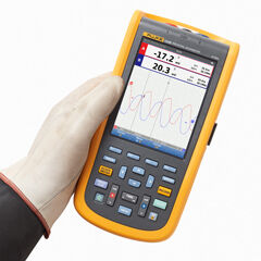
The Fluke 190 Series III portable oscilloscope specifications illustrate how manufacturers combine bandwidth options, real-time sampling, memory, and recording features across different models.
Even when bandwidth and sampling rate meet your requirements, other parts of the measurement system can affect the result.
Memory depth determines how many samples the instrument can store for a waveform record. At a fixed sampling rate, deeper memory allows a longer record while preserving the same sample interval.
For example, a technician investigating a fault that occurs after several milliseconds of normal operation needs enough memory to retain both the lead-up and the event. Otherwise, the captured waveform may show the disturbance without enough context to explain it.
Some oscilloscopes adjust the sampling rate when the technician changes the time base or acquisition settings. Review these trade-offs before collecting important data.
The probe forms part of the complete measurement system. Its bandwidth, attenuation, capacitance, and connection method can affect the waveform reaching the instrument.
A probe with insufficient bandwidth may soften fast edges. Excessive probe loading can also change the behavior of a sensitive circuit.
Therefore, check probe specifications alongside oscilloscope specifications. Use appropriate accessories and connection techniques for the circuit under test.
When measuring several signals simultaneously, verify the sampling rate available per channel. Some instruments reduce their maximum sampling rate when more channels operate at once.
This matters when comparing control inputs and outputs, monitoring multiple phases, or investigating the timing relationship between signals. A specification that applies to one active channel may not apply to the complete measurement setup.
Before comparing models, define the application’s actual requirements. The following checklist helps narrow the options.
These checks help avoid two common mistakes: choosing insufficient performance for demanding signals and paying for capabilities that do not improve the measurements you actually perform.
For additional information about test instruments and measurement solutions, visit the TRUEPOINTLAB website. If you are investigating sporadic shutdowns or unexpected voltage changes, the related guide on capturing intermittent electrical faults with a Fluke oscilloscope explains how trigger settings and recording methods support the diagnostic process.
Bandwidth describes the analog input’s frequency response. Sampling rate describes how often the instrument digitizes the signal. Both affect how accurately an oscilloscope can represent a waveform.
Not necessarily. A higher rate can provide more waveform detail, but it cannot compensate for insufficient bandwidth, poor probe performance, or inadequate memory.
It depends on the signal frequency, edge speed, and required measurement accuracy. For waveform-shape analysis, five times the fundamental frequency is a common starting point, but fast transitions may require a separate rise-time assessment.
Choose a rate that provides enough samples to examine the fastest relevant signal features. Consider the signal’s frequency content, edge speed, acquisition mode, and the number of active channels.
Yes. An unsuitable trigger, insufficient memory, a low effective sampling rate, or an inappropriate probe can prevent the instrument from capturing or displaying the event properly.
Understanding sampling rate and bandwidth makes oscilloscope selection more practical and precise. By considering these specifications alongside memory, probes, acquisition features, and electrical safety, technicians can choose equipment that better matches their industrial measurement tasks. TRUEPOINTLAB provides a useful starting point for exploring test and measurement equipment based on your application’s requirements.
TruePointLab.© 2026. All right reserved