Call us now: +1(800) 123 4567
Email: oesus@support.com

A pressure transmitter displays an unexpected value, a PLC shows a reading that does not match the field instrument, or a flow indicator remains fixed despite changing process conditions. These problems can disrupt operations, but replacing the transmitter immediately may not solve the underlying issue. The fault could originate in the wiring, loop power supply, analog input configuration, or transmitter itself.
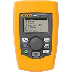
A loop calibrator helps engineers investigate these problems by measuring or generating known current signals. When technicians test a 4–20 mA instrument loop systematically, they can identify signal discrepancies, verify control-system responses, and narrow down the source of a fault.
This guide explains how to test a 4–20 mA loop using a loop calibrator, which test methods to choose, how to interpret the results, and which precautions help maintain reliable measurements.
A 4–20 mA current loop carries measurement information from a field instrument to a receiving device, such as a programmable logic controller (PLC), distributed control system (DCS), or process indicator.
The transmitter converts a measured process variable into an electrical current. For a typical linear configuration, 4 mA represents the lower range value and 20 mA represents the upper range value. The control system then converts that current into an engineering unit.
For example, consider a pressure transmitter configured for a range of 0–10 bar.
These values assume a linear relationship and a correctly configured input channel. Other configurations, including square-root extraction for certain flow measurements, can change how the receiving system interprets the current.
A correct transmitter output does not guarantee a correct control-room reading. Wiring resistance, loose terminals, an incorrect input range, a faulty analog input, or incorrect scaling can create discrepancies.
Testing the loop at different points helps engineers distinguish between a signal-generation problem and a signal-reception problem. For an overview of the instrument’s broader role, see what a loop calibrator does and when engineers need one.
Before connecting the instrument, identify what you need to verify. A loop calibrator may offer several functions, and each serves a different purpose.
Use current measurement when you want to determine what the transmitter actually sends through the circuit.
For example, a transmitter should produce 12 mA at the midpoint of its configured range. If the calibrator measures 11.2 mA, investigate the process condition, transmitter configuration, and measurement uncertainty before deciding whether the output falls outside the permitted tolerance.
The connection method matters. Depending on the circuit, you may need to open the loop and insert the calibrator in series. Follow the instrument manual and the approved site procedure to avoid interrupting critical signals or connecting the meter incorrectly.
Current sourcing allows the calibrator to generate a controlled signal for testing a compatible receiving device.
This method is particularly useful when you suspect a PLC analog input, indicator, or control-system configuration problem. Instead of relying on the field transmitter, you supply known currents and compare the displayed values.
For example, apply 4 mA, 12 mA, and 20 mA according to the approved test procedure. If the PLC displays the wrong engineering values, investigate the input configuration, wiring, and scaling.
Current simulation makes the calibrator behave like a transmitter within a loop that receives power from an external source. This function helps technicians test a receiving circuit without requiring the actual transmitter to generate the signal.
Sourcing and simulation are not interchangeable. Sourcing provides current directly, while simulation operates within a suitably powered loop. Confirm the circuit design, calibrator mode, terminal connections, and power requirements before testing.
A consistent procedure helps reduce connection errors and makes results easier to compare. The following workflow covers a typical signal check, but the site’s approved procedure and equipment manuals take priority.
Identify the transmitter, receiving input, power supply, and wiring arrangement. Check the loop diagram and instrument documentation to determine whether the circuit uses a two-wire transmitter, a separate power supply, or another configuration.
Before connecting the calibrator:
Never assume that a 4–20 mA loop is safe to disconnect simply because it carries a low-level signal. Opening a loop can interrupt monitoring or control.
Check the configured lower range value (LRV) and upper range value (URV). These values define the process measurement corresponding to 4 mA and 20 mA in a standard linear mapping.
For a transmitter with a 0–100°C range, calculate the expected current using:
Expected current = 4 mA + [(process value − LRV) ÷ (URV − LRV)] × 16 mA
At 25°C, the expected current is 8 mA. At 50°C, it is 12 mA, and at 75°C, it is 16 mA.
This calculation assumes a linear relationship and a standard 4–20 mA range. Confirm any special transmitter configuration before applying these values.
Select measurement, source, or simulation according to the test objective. Follow the manufacturer’s wiring diagram and verify polarity where applicable.
If you need to measure the actual transmitter output, use the approved current-measurement arrangement. If you need to test the receiving input independently, use sourcing or simulation as appropriate.
Do not connect a current source across a powered circuit unless the instrument instructions explicitly permit that arrangement. An incorrect connection can damage equipment or create misleading readings.
For a basic linear loop check, use the lower endpoint, midpoint, and upper endpoint. Additional points can provide better evidence when the procedure requires a more detailed assessment.
For a 0–100°C range, the test points are:
At each point, compare the calibrator reading with the expected value and the control system’s displayed value. Record any deviation and determine whether it exceeds the applicable acceptance criteria.
After testing, return the loop to its required operating configuration. Reconnect any removed wiring, restore isolation controls according to site procedure, and confirm that the control system receives a plausible signal.
Document the instrument identification, test method, test points, readings, acceptance criteria, and corrective actions. Clear records make it easier to identify recurring faults and support maintenance decisions.
A loop calibrator provides useful evidence, but engineers must interpret each result in the context of the complete circuit.
If the transmitter produces an unexpected current, check the process conditions, transmitter range settings, supply voltage, wiring, and configuration. Where necessary, test the transmitter against an appropriate physical reference.
For instance, a pressure transmitter may output 10 mA when the expected value is 12 mA. That discrepancy does not automatically prove transmitter failure. The actual pressure, configured range, and measurement uncertainty may explain part of the difference.
If a known current reaches the input but the PLC displays an incorrect process value, investigate the receiving side.
Possible causes include:
A controlled source test can help separate these issues from transmitter performance.
Intermittent signals may indicate loose connections, damaged cables, unstable power, electrical interference, or an instrument fault. Inspect the circuit under the conditions allowed by the site’s procedures.
Do not rely on a single reading if the fault occurs intermittently. Where the calibrator supports suitable monitoring functions, observe the signal over time and correlate changes with operating conditions.
Finally, distinguish calibration from verification. A loop test may confirm that a signal or display responds as expected, but formal calibration requires an appropriate procedure, defined tolerances, and documented results. Review calibration versus verification to understand how these activities differ.
The right loop calibrator should match the team’s test procedures rather than simply offer the largest number of functions.
Start by confirming the following requirements:
A calibrator’s advertised accuracy alone does not establish that every test will be valid. The team must also consider the reference instrument’s uncertainty, test setup, operating conditions, and the accuracy requirements of the device under test.
For formal calibration work, establish acceptance criteria before starting and follow the applicable quality procedures. A suitable instrument combined with a repeatable test method provides more useful evidence than a quick signal check without documented limits.
Testing a 4–20 mA instrument loop with a loop calibrator helps engineers determine whether a problem originates in the transmitter, wiring, power supply, or receiving control system. The most reliable approach starts with the circuit diagram, selects the correct measurement or simulation method, checks multiple test points, and records the results against defined acceptance criteria.
If your team is reviewing its instrumentation procedures or selecting test equipment, visit TRUEPOINTLAB to explore resources related to industrial measurement and calibration. Matching the equipment to your actual testing requirements can help your maintenance team troubleshoot more consistently and make better-informed decisions.
Identify the circuit configuration, connect the calibrator in the correct mode, test known current points, compare the readings with expected values, and document the results. Follow the instrument manual and site safety procedures throughout the test.
A basic linear test commonly uses 4 mA, 12 mA, and 20 mA to check the lower endpoint, midpoint, and upper endpoint. Additional points may be necessary under the approved procedure.
Yes. A calibrator with a suitable current-source function can test a compatible PLC input by supplying known currents and comparing the displayed engineering values with the expected results.
Loop testing checks signal transmission and reception across some or all of a circuit. Transmitter calibration compares the instrument’s response with an appropriate reference under defined conditions and evaluates its performance against specified tolerances.
Possible causes include incorrect input scaling, a mismatched current range, configuration errors, or a faulty input channel. Verify the current at the appropriate test point and check the receiving system’s configuration before replacing components.
TruePointLab.© 2026. All right reserved