Call us now: +1(800) 123 4567
Email: oesus@support.com

A control system displays an unexpected voltage, a transmitter produces an inconsistent current signal, or a PLC input reports a value that does not match the field instrument. These problems can disrupt industrial processes and make troubleshooting unnecessarily complicated. Without a reliable reference, technicians may struggle to determine whether the fault originates in the instrument, wiring, power supply, or receiving equipment.
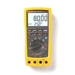
An electrical calibrator helps engineers test electrical signals by measuring or generating known voltage and current values. Depending on its capabilities, it can support instrument verification, loop troubleshooting, commissioning, and calibration procedures across industrial measurement systems.
However, not every electrical calibrator performs the same functions. Some measure signals, others source or simulate them, and multifunction models combine several capabilities. Understanding these differences helps technicians select the right instrument and perform more reliable tests.
An electrical calibrator is a test instrument that generates, measures, or simulates electrical signals used by industrial and electronic equipment. Typical applications include testing voltage outputs, current loops, process transmitters, control-system inputs, and electrical measurement devices.
Depending on the model, an electrical calibrator may support:
These functions serve different purposes. A calibrator that measures voltage does not necessarily generate voltage, and a current source does not automatically support current simulation.
For example, a technician testing a pressure transmitter may need to measure its 4–20 mA output. However, when testing the receiving PLC input independently, the technician may need a calibrator that can generate a known current.
The first step is to identify whether you need to measure an existing signal or generate a controlled signal for testing. That distinction determines the required instrument functions and connection method.
Voltage and current signals both carry information, but they behave differently in practical measurement circuits. Engineers must understand these differences before selecting a test method.
Voltage signals commonly appear in electronic control systems, sensor interfaces, and industrial equipment. Some process instruments use a 0–10 V DC output, where 0 V represents the lower end of a configured range and 10 V represents the upper end.
For example, a sensor configured for 0–100°C might produce 5 V at 50°C if it uses a linear 0–10 V mapping. A calibrator can measure the output voltage and help determine whether it matches the expected value.
When testing voltage, technicians should check the signal reference, input impedance, wiring, and configured range. A voltage reading can change if the measurement setup loads the circuit or uses an incorrect reference connection.
Industrial process instrumentation frequently uses the 4–20 mA current loop. In a standard linear arrangement, 4 mA represents the lower range value, while 20 mA represents the upper range value.
For a pressure transmitter configured from 0 to 10 bar, the expected current at 5 bar is 12 mA. A calibrator can measure the output and help technicians identify deviations from the expected signal.
Current-loop testing requires the correct electrical connection. Depending on the circuit and instrument, technicians may need to insert the measuring device in series rather than connect it across the loop.
Voltage and current signals require different test configurations. Applying the wrong function or connecting the calibrator incorrectly can interrupt the circuit, damage equipment, or produce misleading readings.
Before testing, confirm the signal type, expected range, circuit design, and calibrator specifications. Never assume that a device supports every electrical function simply because its name includes the term electrical calibrator.
A structured voltage test helps engineers distinguish an output problem from a configuration or wiring issue. The exact procedure depends on the instrument and the calibrator’s measurement capabilities.
Review the instrument manual or wiring diagram to identify the expected voltage range, output terminals, signal reference, and operating conditions.
For example, a device may use a 0–10 V DC output, while another uses a narrower range. Confirm the actual specification rather than relying on assumptions based on the application.
Select the appropriate DC voltage measurement function and connect the leads to the specified terminals. Follow the manufacturer’s instructions and applicable site safety procedures.
Check polarity and ensure that the measurement setup does not introduce an unsuitable load. If the circuit uses a shared reference or grounded equipment, consider the grounding arrangement before connecting the instrument.
Operate the device at several known input conditions or use an approved procedure to establish expected output values.
For a linear 0–10 V output representing 0–100°C, expected values include:
Record the measured output and calculate its deviation from the expected value. If the sensor indicates 5.2 V at the midpoint, the difference is +0.2 V. Determine whether that deviation exceeds the applicable tolerance before declaring a failure.
If the voltage differs from the expected value, inspect the output configuration, wiring, supply conditions, connections, and receiving input. Where necessary, test the signal source separately from the control system.
A single voltage reading cannot always identify the root cause. Compare measurements at appropriate points in the circuit and use the equipment documentation to guide further testing.
Current-output testing is particularly important for industrial transmitters and analog control systems. A calibrator with suitable current measurement, sourcing, or simulation functions can help engineers investigate different parts of the loop.
Determine whether the transmitter uses an external supply, an internally powered input, or another arrangement. Confirm the loop’s wiring diagram and whether the circuit must remain active during the test.
If the loop controls a critical process, obtain the required authorization before disconnecting or interrupting it.
Select the correct current-measurement mode and follow the specified connection method. Many conventional current measurements require the meter to form part of the circuit, so incorrect parallel connections can cause problems.
For a 0–100% process range, a standard linear loop should produce approximately:
Compare the measured values with the expected signal and the receiving system’s display.
When testing a PLC or control-system input independently, a compatible calibrator can generate a known current. The technician then compares the displayed engineering value with the expected result.
For example, applying 12 mA to an input configured for 0–100 bar should produce 50 bar under standard linear scaling. If the display shows a different value, investigate the input configuration, scaling, wiring, or channel condition.
Current sourcing and simulation differ in how they interact with the circuit’s power supply. Always select the correct mode and follow the calibrator’s connection diagram.
For a more detailed procedure, see how to test a 4–20 mA instrument loop with a loop calibrator.
Even a capable calibrator cannot compensate for an incorrect test setup. Several common mistakes can produce unreliable results.
Selecting the wrong measurement function can lead to incorrect connections or misleading readings. Verify whether the task requires voltage measurement, current measurement, sourcing, or simulation before connecting the instrument.
Ignoring the circuit configuration can disrupt a powered loop or create an unsuitable measurement path. Review the wiring diagram and understand how the transmitter, supply, and receiving input interact.
Overlooking input scaling can make a correct electrical signal appear incorrect at the control system. Confirm the configured lower and upper range values and the conversion from electrical signal to engineering units.
Using an unsuitable reference instrument can make it difficult to evaluate whether a signal meets its required tolerance. Check the calibrator’s specifications, calibration status, and measurement uncertainty.
Failing to document the results makes it harder to identify recurring faults or demonstrate that a test met the required procedure. Record test points, measured values, expected values, acceptance criteria, and corrective actions.
To improve consistency, maintenance teams should establish clear test procedures and use equipment suited to the measurement task. Additional guidance is available in this article on reducing measurement errors with industrial calibration equipment.
The best electrical calibrator depends on the signals your team tests, the accuracy required, and the working environment.
Start by listing the instruments and circuits that need testing. Identify their voltage and current ranges, signal types, connection arrangements, and acceptance tolerances.
Next, evaluate these capabilities:
A basic electrical calibrator may suit teams that mainly check voltage and current signals. However, technicians who maintain process transmitters may benefit from a model that combines current measurement, sourcing, simulation, and other relevant functions.
Avoid choosing equipment based on the number of functions alone. Instead, match the specifications to the actual work and consider the uncertainty of the complete measurement process.
An electrical calibrator helps engineers test voltage and current outputs, investigate signal discrepancies, and verify the operation of compatible control-system inputs. Reliable results depend on selecting the correct function, understanding the circuit, comparing readings against expected values, and documenting the findings.
Before choosing a calibrator, review your team’s signal types, required accuracy, test procedures, and field conditions. Visit TRUEPOINTLAB to explore industrial measurement and calibration resources that can support your equipment selection and maintenance planning.
An electrical calibrator measures, generates, or simulates electrical signals such as DC voltage and current. Engineers use it to test process instruments, transmitters, and control-system inputs.
Yes, if the model supports both functions and the required ranges. Check whether it provides measurement, sourcing, or simulation capabilities for each signal type.
Use a suitable calibrator in the correct current-measurement configuration, compare readings with expected values, and follow the loop’s wiring and safety procedures.
Measuring determines the signal produced by a device. Sourcing generates a controlled signal that technicians can apply to a compatible circuit to test its response.
The interval depends on usage, performance history, operating conditions, accuracy requirements, and the organization’s quality procedures. Review documented results and risk when setting the interval.
TruePointLab.© 2026. All right reserved