Call us now: +1(800) 123 4567
Email: oesus@support.com

A process control system can display a temperature, pressure, or flow reading that looks perfectly normal while the actual measurement signal tells a different story. A faulty transmitter, incorrect scaling, damaged wiring, or a controller input problem can all produce unreliable readings. Without a systematic test, engineers may spend hours troubleshooting the wrong component.
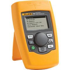
A loop calibrator helps engineers identify these problems by testing the electrical signals used in industrial instrumentation, particularly the widely used 4–20 mA current loop. Depending on the model, it can measure current, generate or simulate signals, and help technicians verify whether a transmitter and control system communicate correctly.
Understanding what a loop calibrator does—and when to use one—helps maintenance teams troubleshoot more efficiently, verify instrumentation performance, and reduce unnecessary component replacement. This guide explains its main functions, practical applications, and the factors engineers should consider when selecting a suitable instrument.
A loop calibrator is an electrical test instrument designed to measure, generate, or simulate signals in industrial process-control loops. Engineers use it to check instrumentation such as pressure transmitters, temperature transmitters, flow meters, and other devices that communicate through analog current signals.
Most industrial applications use the 4–20 mA current loop. In this arrangement, 4 mA commonly represents the lower end of the configured measurement range, while 20 mA represents the upper end. The control system converts the current into an engineering value, such as degrees Celsius, bar, or liters per minute.
For example, a pressure transmitter configured for 0–10 bar might produce:
These values provide a straightforward way to check whether the signal corresponds to the expected measurement.
However, a loop calibrator does more than check current. Depending on its capabilities, it can source current, simulate a transmitter output, measure loop current, or supply loop power. Some models also support voltage measurement and additional electrical functions.
The key distinction is that a loop calibrator tests the electrical signal path, not necessarily the complete physical measurement process. Testing a pressure transmitter’s output, for instance, does not automatically establish that its pressure sensor measures applied pressure accurately.
The exact functions depend on the instrument model. Nevertheless, several capabilities make loop calibrators useful for routine maintenance and commissioning.
A calibrator can measure the current flowing through a loop to determine whether a transmitter or controller produces the expected signal.
Suppose a flow transmitter should output 12 mA at a particular operating condition, but the calibrator reads 9.6 mA. The discrepancy indicates that the team should investigate the transmitter, configuration, wiring, or operating conditions before assuming the controller has failed.
Current measurement provides evidence for troubleshooting, although engineers must interpret the reading within the loop’s design and operating requirements.
A calibrator with current-sourcing capability can generate a known signal independently of the transmitter. Engineers can use this output to test receiving equipment, including PLC analog inputs, distributed control systems (DCS), and panel indicators.
For example, a technician can inject 4 mA, 12 mA, and 20 mA into a compatible input circuit. The technician then checks whether the control system displays the expected minimum, midpoint, and maximum values.
This approach helps separate an input-channel problem from a transmitter problem. If the controller displays the wrong value despite receiving a verified test current, the team can investigate channel configuration, wiring, or scaling.
Current simulation allows a calibrator to behave like a two-wire transmitter under test conditions. The calibrator regulates the loop current while an external loop supply provides the necessary electrical power, subject to the instrument’s operating requirements.
This function helps engineers test how a control system responds to different process values without requiring the actual transmitter to produce those signals.
However, simulation and sourcing are not interchangeable. Sourcing generally provides current directly, while simulation works within a powered loop. Technicians should follow the instrument manual and confirm the required wiring before connecting either mode.
Some loop calibrators provide a loop-power function, allowing technicians to energize a compatible two-wire transmitter while measuring its output current.
This capability can simplify field testing when a transmitter has no convenient external supply. It can also help engineers identify problems involving missing loop power, incorrect polarity, or an interrupted current path.
Before using this function, technicians should confirm the transmitter’s supply requirements and the calibrator’s voltage limits. They should also isolate circuits where required by the site’s electrical safety procedures.
A loop calibrator becomes particularly valuable when an industrial process depends on reliable analog signals and technicians need to determine whether an instrument, cable, or receiving device causes a problem.
When installing a new transmitter, engineers need to verify that its signal reaches the intended control-system input and that the displayed process value matches the configured range.
A practical commissioning check includes:
These checks help identify problems before the equipment enters normal operation.
Routine maintenance teams can use loop calibrators to verify instrument signals according to an established maintenance plan. For example, a technician might check a pressure transmitter during a scheduled shutdown and compare its output at several test points with the expected values.
The required frequency depends on the instrument’s criticality, operating environment, history of drift, manufacturer guidance, and applicable quality procedures. Not every transmitter requires the same maintenance interval.
A well-organized team should also maintain equipment identification, test results, instrument status, and due dates. These practices support consistent decisions across the plant. Teams can strengthen their procedures by reviewing industrial calibration equipment for plant teams.
A loop calibrator can help investigate symptoms such as:
For example, if a pressure transmitter produces the expected current but the control system displays the wrong pressure, the problem may involve input scaling or configuration rather than the transmitter itself.
By testing individual parts of the signal path, engineers can narrow down the cause instead of replacing components without sufficient evidence.
A structured procedure improves measurement consistency and reduces the risk of incorrect connections. The following example illustrates a basic current-loop check for a compatible 4–20 mA instrument.
Review the wiring diagram, transmitter documentation, and control-system configuration. Determine whether the circuit uses an externally powered transmitter, an internally powered input, or another arrangement.
Also confirm whether the test requires current measurement, current sourcing, or simulation. Selecting the wrong mode can interrupt the loop or produce misleading readings.
Follow the manufacturer’s connection diagram and the site’s isolation procedures. Use the correct terminals and observe polarity where applicable.
Before making connections, verify that the circuit’s electrical conditions fall within the calibrator’s ratings. Never assume that a low-current signal circuit is automatically safe to connect without checking its configuration.
For a 4–20 mA loop, engineers commonly check the lower endpoint, midpoint, and upper endpoint. These correspond to 4 mA, 12 mA, and 20 mA when the configured range uses those endpoints.
Compare each applied or measured current with the value displayed by the receiving system. If the values differ, determine whether the discrepancy originates in the signal, wiring, input configuration, or engineering-unit scaling.
Document the instrument identification, test conditions, readings, acceptance criteria, and any corrective action. If the test forms part of a formal calibration, follow the organization’s approved procedure and record the required uncertainty and traceability information.
A successful signal check does not automatically establish that the transmitter’s entire measurement chain meets its accuracy specification. Where necessary, engineers must test the sensor against a suitable physical reference, such as a pressure standard or temperature reference.
Not every maintenance team needs the same instrument. The best choice depends on the equipment under test, the site’s working environment, and the required level of measurement confidence.
Start by listing the tasks the team performs most frequently. A technician who mainly checks existing current loops may need reliable current measurement and loop-power capability. A commissioning engineer may also need sourcing and simulation functions to test control-system inputs.
Consider these features:
An instrument’s stated accuracy should suit the tolerance of the device being tested. A calibrator with insufficient accuracy can make it difficult to determine whether a transmitter meets its specification.
Also distinguish between a manufacturer’s accuracy specification and the instrument’s current calibration status. Even a capable calibrator requires appropriate calibration, maintenance, and verification according to its intended use.
For measurement systems that require formal traceability, consult the National Institute of Standards and Technology’s guidance on metrological traceability. The applicable procedure should define the evidence needed for the specific measurement.
Finally, consider who will use the calibrator and how often. A straightforward instrument may suit routine maintenance, while a team that handles diverse transmitters and commissioning tasks may benefit from broader sourcing, simulation, and diagnostic capabilities.
A loop calibrator helps industrial engineers test 4–20 mA signals, simulate transmitter outputs, check control-system inputs, and investigate instrumentation problems. Its greatest value comes from helping technicians isolate faults systematically rather than replacing components based on symptoms alone.
Before selecting a model, identify the signal types, test procedures, accuracy requirements, and documentation practices that matter in your facility. TRUEPOINTLAB can serve as a starting point for exploring instrumentation and measurement equipment suited to industrial applications. A clear understanding of your testing requirements will help your team choose equipment that supports dependable maintenance and more consistent measurement results.
A loop calibrator measures, generates, or simulates industrial current signals, especially 4–20 mA loops. Engineers use it to test transmitters, PLC inputs, indicators, and process-control circuits.
No. A multimeter measures electrical quantities such as voltage, current, and resistance. A loop calibrator adds specialized functions for generating or simulating process-control signals, depending on the model.
Yes, if the instrument supports the required measurement or simulation functions. However, testing the electrical output alone does not necessarily verify the transmitter’s physical sensing accuracy.
Sourcing supplies a controlled current directly to a compatible circuit. Simulation makes the calibrator behave like a transmitter within a loop powered by an external supply. The correct mode depends on the circuit design.
The interval depends on its usage, accuracy requirements, environmental conditions, performance history, and quality procedures. Organizations should establish suitable intervals and review them using documented calibration results and risk.
TruePointLab.© 2026. All right reserved