Call us now: +1(800) 123 4567
Email: oesus@support.com

A temperature sensor can continue displaying a plausible value even when its measurement has drifted beyond the permitted tolerance. In a production line, that error may affect process control, product quality, or equipment protection. Replacing the sensor without testing it can waste maintenance time, while trusting an inaccurate reading can create more serious operational problems.
A temperature calibrator helps technicians verify whether resistance temperature detectors (RTDs) and thermocouple sensors deliver reliable measurements. By exposing a sensor to a controlled temperature and comparing its indication with a suitable reference, engineers can identify measurement errors and determine whether the sensor meets its specified requirements.
However, RTDs and thermocouples work differently, so technicians must account for their electrical characteristics, connection methods, and response times. This guide explains how to verify both sensor types, select suitable calibration equipment, interpret results, and avoid common testing errors.
Before testing a temperature sensor, technicians need to understand how it measures temperature. The sensor type determines the electrical signal, connection arrangement, and verification method.
An RTD measures temperature through a change in electrical resistance. Platinum RTDs, particularly Pt100 and Pt1000 sensors, are common in industrial applications because they provide predictable resistance-temperature relationships.
A Pt100 sensor has a nominal resistance of 100 ohms at 0°C, while a Pt1000 has a nominal resistance of 1,000 ohms at the same reference temperature. Their resistance changes as temperature changes, following the relevant sensor characteristic.
RTDs may use two-, three-, or four-wire connections. Two-wire circuits include lead resistance in the measurement, while three- and four-wire arrangements help compensate for lead resistance when used with compatible measuring equipment.
During verification, technicians compare the temperature indicated by the connected measurement system with the reference temperature. They should also consider the RTD element, wiring, transmitter, and input configuration because any of these can contribute to an incorrect reading.
A thermocouple uses two dissimilar conductors joined to produce a thermoelectric voltage related to the temperature difference between the measuring junction and the reference junction.
Common industrial types include K, J, T, and N. Each type has its own temperature characteristics and material requirements. The receiving instrument must use the correct thermocouple type and suitable reference-junction compensation.
For example, a Type K thermocouple connected to an input configured for Type J may produce an incorrect temperature reading even when the sensor itself functions properly.
RTDs measure resistance, while thermocouples generate a temperature-dependent voltage. Therefore, technicians must use the appropriate electrical measurement method and confirm that the complete measurement system matches the sensor type.
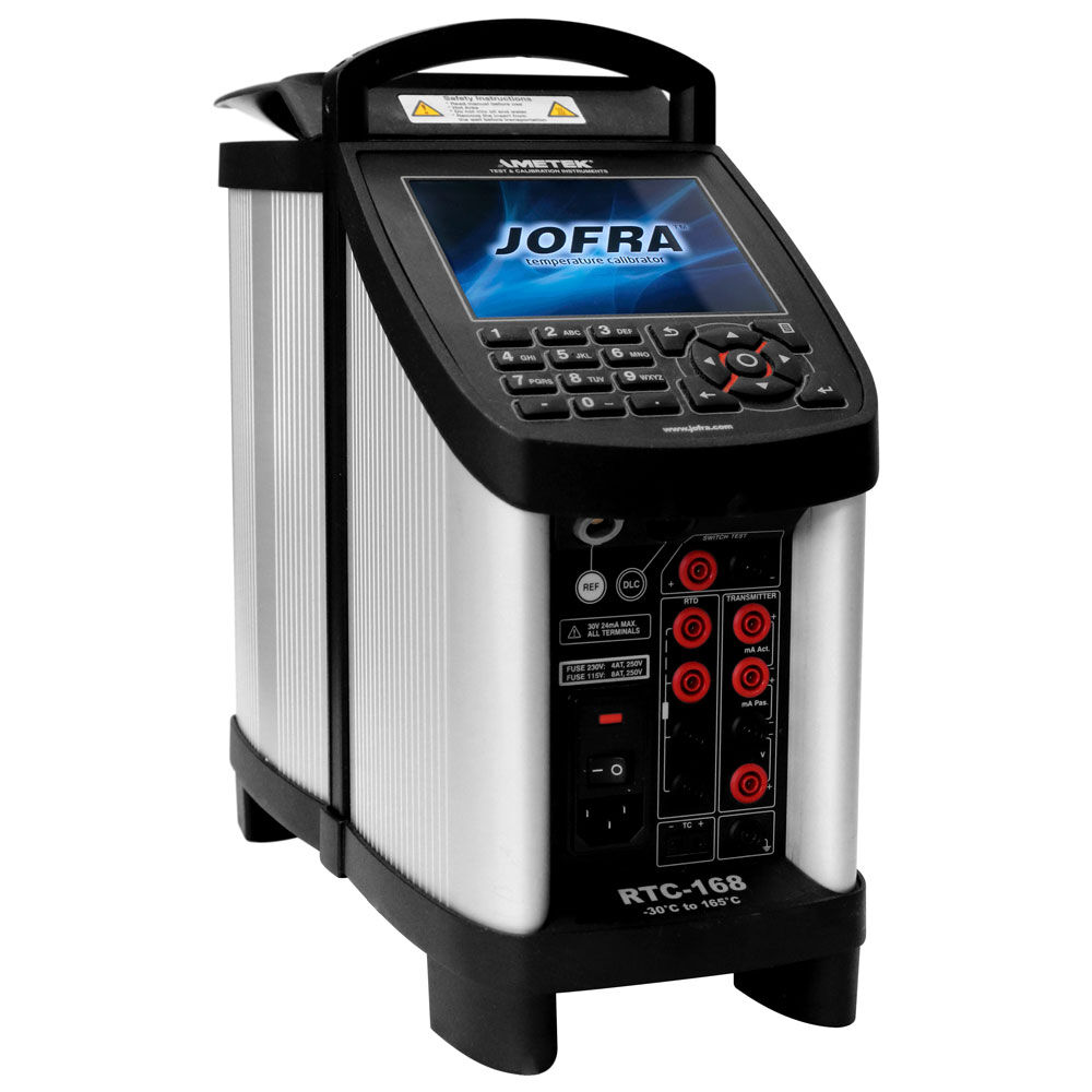
A suitable temperature calibrator provides a controlled temperature environment and supports the sensor dimensions, range, and performance requirements of the test.
A dry-block calibrator heats or cools a metal block containing wells for temperature probes. It suits many field applications because technicians can transport it between equipment locations without managing bath fluid.
Dry blocks work well when the probe fits the selected insert and the required immersion depth. However, differences in probe diameter, thermal contact, and immersion can affect the results.
A liquid bath surrounds the immersed sensor with a controlled fluid. Depending on its design and operating conditions, it can provide good temperature uniformity and accommodate a wider range of probe shapes.
Baths may suit laboratory comparisons involving several sensors. Nevertheless, technicians must manage fluid compatibility, cleanliness, and safe operating limits.
Before choosing a calibrator, review:
For a more detailed comparison of the two temperature-source designs, see how to choose between a dry-block and liquid-bath temperature calibrator.
RTD verification compares the sensor’s indicated temperature with a reference at selected temperature points. The procedure may test the sensing element alone or the complete measurement chain, depending on the maintenance objective.
Identify the RTD type, nominal resistance, temperature range, and wiring arrangement. Inspect the probe, connector, extension cable, and terminals for damage or loose connections.
Check whether the measuring instrument supports the correct RTD type and wire configuration. An incorrect setting can introduce errors that a temperature-source check alone will not identify.
Insert the RTD and a suitable reference thermometer into the calibrator. Follow the manufacturer’s guidance on immersion depth, sensor spacing, and insert selection.
Allow the system to reach the required stability. A displayed setpoint does not necessarily mean the probe and reference have reached thermal equilibrium.
Select test points across the RTD’s working range. For example, a sensor used between 0°C and 200°C might require checks near 0°C, 100°C, and 200°C, depending on the approved procedure.
At each point, record the reference temperature and the RTD’s indicated value. Calculate the deviation:
Deviation = Sensor indication − Reference temperature
If the reference reads 100.0°C and the RTD system indicates 100.7°C, the deviation is +0.7°C. Compare that result with the applicable tolerance and measurement uncertainty before deciding whether the sensor passes.
If the result falls outside tolerance, check the wiring arrangement, lead resistance compensation, connections, transmitter configuration, and sensor condition.
A resistance measurement can help distinguish an electrical fault from a temperature-response problem. However, resistance values must be interpreted against the sensor’s specified characteristic and the actual measurement conditions.
Thermocouple verification requires attention to sensor type, extension wiring, polarity, and reference-junction compensation. A temperature source alone does not guarantee that the complete electrical measurement chain produces the correct temperature.
Check the sensor identification and verify that the measuring instrument uses the correct thermocouple configuration. Confirm that extension or compensating wires match the thermocouple type and that polarity remains correct throughout the circuit.
Incorrect wire types or connections can introduce errors that become more noticeable at particular temperatures.
Place the thermocouple and reference thermometer in the calibrator’s working zone. Ensure that the measuring junction reaches the intended temperature and that the reference sensor provides a suitable comparison.
Allow enough time for stabilization. The response time depends on probe construction, diameter, sheath material, and immersion depth.
Test at the points specified by the calibration procedure. At each point, compare the thermocouple system’s indication with the reference temperature.
For example, if the reference reads 200.0°C and the thermocouple system indicates 203.0°C, the deviation is +3.0°C. Determine whether that deviation meets the sensor’s acceptance criteria.
If the thermocouple fails, inspect polarity, wiring materials, terminal connections, input configuration, and reference-junction compensation.
Thermocouple output also depends on the temperature difference between junctions. Consequently, an electrical measurement that ignores reference-junction conditions may not provide a valid assessment of the complete system.
Even a suitable temperature calibrator can produce misleading results if technicians overlook the test setup.
Insufficient immersion can expose part of the sensor to a different temperature, particularly when the probe has a long stem or large thermal mass. Follow the manufacturer’s immersion guidance and consider stem conduction.
Poor thermal contact can affect dry-block results. Choose an appropriate insert and avoid assuming that every probe will achieve the same thermal response in the same well.
Premature readings can create apparent deviations because the sensor has not stabilized. Allow both the reference and the sensor under test to reach the required conditions.
Incorrect electrical configuration can produce errors unrelated to the sensing element. Verify RTD wiring compensation, thermocouple type, polarity, extension wiring, and transmitter settings.
Ignoring measurement uncertainty can lead to unjustified pass-or-fail decisions. Consider the reference instrument’s uncertainty, calibrator performance, sensor stability, and the acceptance rule specified by the organization.
Finally, distinguish a sensor check from a formal calibration. Verification determines whether results satisfy defined requirements. Calibration establishes the relationship between indications and reference values under specified conditions. For more information, read calibration versus verification for industrial equipment.
A repeatable process helps maintenance teams compare results across technicians, instruments, and service intervals.
Start by documenting each sensor’s identification, type, working range, required tolerance, and verification frequency. Establish suitable test points and specify the reference equipment, stabilization criteria, and acceptance rules.
During each test, record the reference temperature, sensor indication, calculated deviation, and relevant environmental or setup conditions. If a sensor fails, document the investigation, corrective action, and retest results.
Also maintain the calibration status of the reference thermometer and temperature calibrator. Review historical results to identify recurring drift or failures that may justify a revised maintenance interval.
The appropriate interval depends on sensor criticality, operating conditions, historical performance, and applicable quality requirements. A sensor exposed to repeated thermal cycling may require a different approach from one operating under stable conditions.
Teams reviewing their broader measurement requirements can explore industrial calibration equipment for plant teams to support consistent equipment selection and maintenance planning.
Verifying RTD and thermocouple sensors with a temperature calibrator requires more than comparing two displayed values. Technicians must select a suitable temperature source, confirm sensor configuration, allow adequate stabilization, test appropriate points, and evaluate deviations against defined tolerances.
RTDs require attention to resistance measurement and lead compensation, while thermocouples require correct sensor types, wiring, polarity, and reference-junction compensation. A structured procedure helps teams identify errors and maintain more dependable temperature measurements.
Visit TRUEPOINTLAB to explore industrial measurement and calibration resources for your instrumentation work. Matching the equipment and verification procedure to your application helps support consistent maintenance decisions.
Place the RTD and a suitable reference thermometer in a controlled temperature source, allow them to stabilize, and compare their readings at defined test points. Evaluate deviations against the applicable tolerance.
Expose the thermocouple and a suitable reference sensor to known temperatures. Confirm the thermocouple type, wiring polarity, extension-wire compatibility, and reference-junction compensation before comparing readings.
Yes. A suitable temperature source can test both sensor types, but the electrical measurement equipment and connection methods must support the specific RTD or thermocouple configuration.
The number depends on the sensor’s working range, required tolerance, and approved procedure. Three points may suit a basic check, while demanding applications can require additional points.
Possible causes include sensor drift, damaged wiring, poor connections, incorrect input configuration, insufficient immersion, unstable temperature, or an unsuitable reference setup. Investigate the complete measurement chain before replacing the sensor.
TruePointLab.© 2026. All right reserved