Call us now: +1(800) 123 4567
Email: oesus@support.com

An industrial fault rarely occurs at a convenient moment. A motor drive may produce an unexpected signal, a controller may reset intermittently, or a sensor output may change just before a machine stops. When technicians investigate these problems, the oscilloscope must capture enough information to reveal what happened.
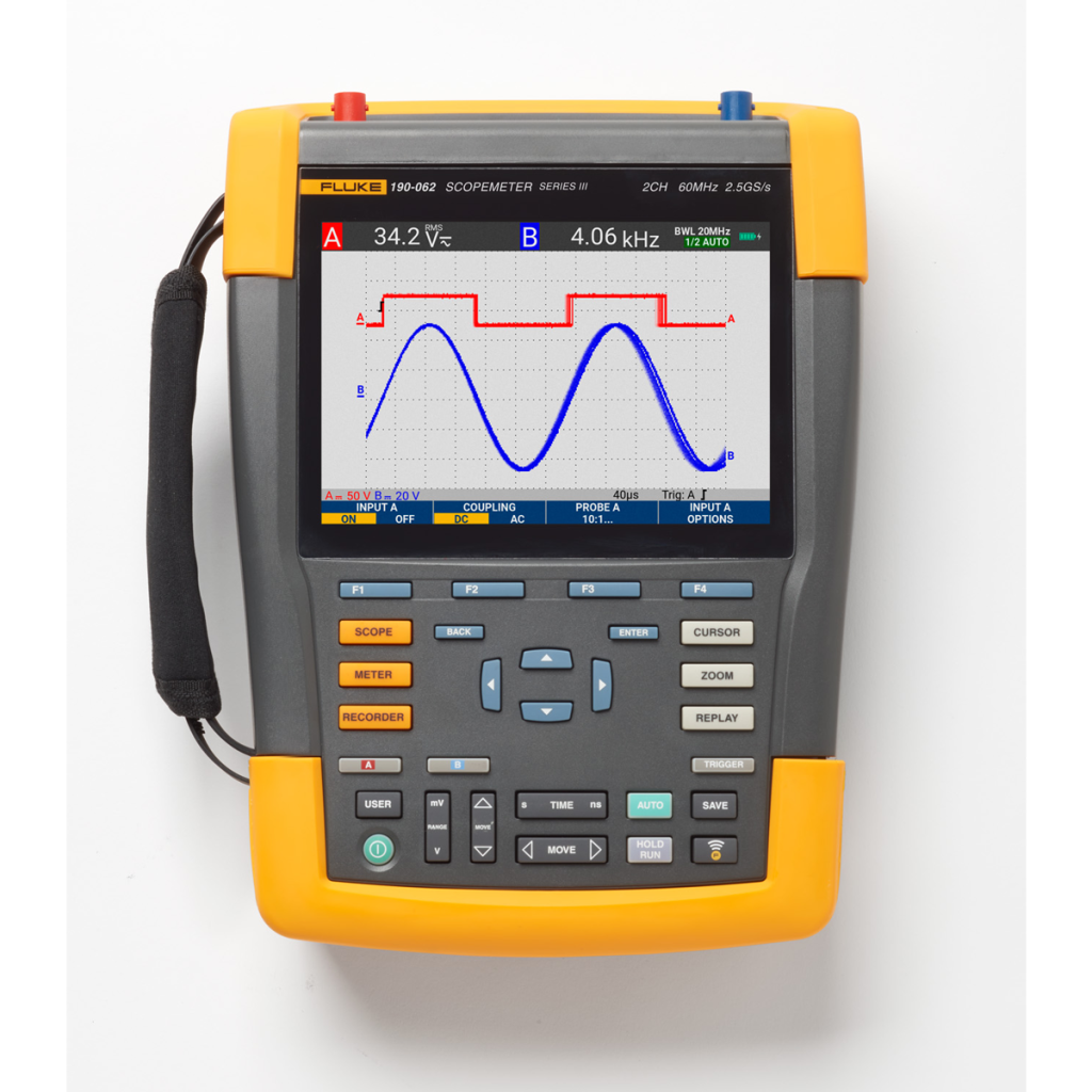
If you plan to buy a Fluke ScopeMeter, three specifications deserve particular attention: channel count, record length, and sampling rate. These features influence how many signals you can compare, how much waveform information you can retain, and how precisely the instrument represents changes over time.
However, choosing the highest specification in every category does not necessarily produce the best instrument for your application. The right combination depends on the signals you measure, the faults you investigate, and the complexity of your diagnostic workflow.
This guide explains how to evaluate these specifications and compare ScopeMeter models for practical industrial field testing.
Channel count determines how many input signals an oscilloscope can acquire simultaneously under its supported operating conditions. For field diagnostics, the appropriate number depends on whether you need to investigate one signal independently or compare several signals to understand a fault.
A single-channel measurement can help when you need to inspect a control voltage, examine a sensor waveform, or investigate an individual electrical signal.
However, industrial faults often involve relationships between signals. For example, a technician diagnosing a motor-control problem may need to compare a command signal with a feedback signal. Observing both can help establish whether the signals change in the expected sequence.
In this situation, two-channel acquisition can provide more useful evidence than examining each signal separately.
More channels can help when a diagnostic task involves several related signals, such as:
Nevertheless, more channels do not automatically mean better measurements. Some instruments have different performance limits depending on the number of active channels, acquisition mode, or configuration.
Before purchasing, check the exact model’s channel count, supported input combinations, and any restrictions that affect simultaneous acquisition.
Also distinguish oscilloscope channels from multimeter functions. A ScopeMeter may combine waveform acquisition with additional measurement capabilities, but those functions do not necessarily operate as independent oscilloscope channels.
Choose enough channels for your actual diagnostic procedures, with some allowance for tasks your team regularly expects to encounter.
Sampling rate describes how frequently an oscilloscope digitizes an incoming signal. The instrument uses these samples to reconstruct a waveform for display and analysis.
A higher sampling rate can provide more time-domain detail, particularly when the signal changes rapidly. However, sampling rate alone does not determine the quality of a measurement.
Consider a technician investigating a switching circuit. The signal may contain rapid transitions that reveal important information about the circuit’s operation. If the instrument samples too slowly for the task, it may miss details or represent the waveform inaccurately.
Sampling requirements depend on the signal’s frequency content, transient behavior, and the information you need to extract.
For repetitive signals, the Nyquist principle states that the sampling frequency must exceed twice the highest frequency component to avoid basic aliasing under ideal band-limited conditions. In practice, meeting that minimum does not guarantee an accurate representation of every waveform feature. Fast edges, transient events, and measurement objectives may require substantially higher sampling rates.
When comparing ScopeMeter models, review:
These details matter because a headline sampling rate may not apply under every operating condition.
For a deeper explanation of how these specifications interact, read TRUEPOINTLAB’s guide to oscilloscope sampling rate and bandwidth.
Record length describes how many samples an oscilloscope can retain in an acquisition record. It affects how much signal history you can examine, especially when investigating events that occur over a longer period.
A high sampling rate helps capture fine time-domain detail, while sufficient record length helps preserve that detail across a useful observation window.
Suppose a technician needs to investigate a machine that stops unexpectedly after several seconds of normal operation. The relevant signal may change briefly before the shutdown, so the technician needs enough stored data to inspect the sequence surrounding the event.
A short acquisition record may preserve detailed samples but cover only a limited time interval. A longer record may cover more of the event, although the instrument’s memory and acquisition settings influence the available sampling rate.
For a simplified example, an acquisition containing one million samples at a constant sampling rate of 100 million samples per second spans:
[
\frac{1{,}000{,}000}{100{,}000{,}000}=0.01\text{ seconds}
]
That represents 10 milliseconds of sampled data. The calculation illustrates why record length and sampling rate must be considered together.
Actual instrument behavior depends on the selected model and acquisition configuration.
Before choosing a model, consider whether your troubleshooting involves:
The required record length depends on the event duration and the detail you need to examine. A technician investigating a brief pulse may prioritize fine time resolution, while someone studying a longer control sequence may need a broader observation window.
Check the manufacturer’s specifications to understand the available memory depth and its relationship to sampling rate, channels, and acquisition modes.
These three specifications work together. Comparing them independently can lead to an instrument that looks suitable on paper but struggles with the intended measurement.
Some oscilloscopes share acquisition resources across channels or impose different sampling limits when several channels operate simultaneously. Others specify different memory or sampling capabilities depending on the configuration.
Therefore, do not assume that a model’s maximum sampling rate and maximum record length are always available on every channel at the same time.
Ask the supplier or consult the official manual to determine which combinations the instrument supports.
For a given number of samples, increasing the sampling rate shortens the time represented by the record. Conversely, reducing the sampling rate allows the same number of samples to cover a longer interval.
This creates a practical trade-off. You may need to capture fast signal transitions while preserving enough surrounding information to understand the event.
For example, troubleshooting a controller reset may require examining both a brief voltage disturbance and the signal sequence leading up to it. A suitable acquisition configuration must preserve the relevant details without discarding important context.
Build a shortlist around a realistic task rather than the largest advertised number. Ask:
These questions connect instrument specifications to practical diagnostic needs.
Channel count, sampling rate, and record length cannot compensate for every limitation in waveform capture. Bandwidth and triggering also influence whether the oscilloscope records useful evidence.
Oscilloscope bandwidth describes the instrument’s frequency response. Insufficient bandwidth can attenuate higher-frequency components and distort fast-changing waveforms.
For example, a technician investigating switching behavior in power electronics may need more bandwidth than someone measuring a slowly changing industrial control signal.
Select bandwidth based on the signal characteristics and measurement accuracy required. Also consider probe bandwidth because the probe can limit the performance of the complete measurement setup.
Triggering provides a condition for stabilizing or initiating waveform acquisition around a relevant event. Depending on the model, trigger functions can help technicians investigate signal transitions or other defined conditions.
For an intermittent fault, an appropriate trigger can help capture the event when it occurs rather than requiring the technician to watch the display continuously.
Before purchasing, verify the available trigger types, single-event acquisition capabilities, and storage options. These features may be more important for intermittent troubleshooting than a small increase in maximum sampling rate.
For broader guidance on choosing an instrument for field diagnostics, see how to compare Fluke ScopeMeter models.
Once you understand the technical specifications, compare candidate models against your actual workload. This approach helps you avoid paying attention to headline numbers that do not materially improve your measurements.
For each model, confirm:
Then verify whether the instrument maintains the required performance under the channel and acquisition settings your team will actually use.
Also review the operating manual, warranty terms, technical support arrangements, and included accessories. These practical details influence how effectively the instrument fits your maintenance workflow.
If you are evaluating equipment for industrial applications, explore the technical resources available through TRUEPOINTLAB as part of your research.
Finally, choose the model that meets your essential requirements with a suitable margin for realistic diagnostic tasks. A balanced configuration is generally more useful than maximizing one specification while overlooking another.
The answer depends on how many signals you need to compare simultaneously. One channel may suit individual signal checks, while two or more may help investigate relationships between control, feedback, and other signals. Verify the exact model’s channel configuration.
Sampling rate determines how frequently the instrument digitizes an input signal. It influences how well the instrument represents signal changes, but bandwidth, acquisition settings, and signal characteristics also affect measurement quality.
Record length describes the number of samples retained in an acquisition record. Combined with sampling rate, it determines how much time-domain information the instrument can store for analysis.
No. A higher sampling rate can help capture fast signal changes, but the instrument must also provide suitable bandwidth, record length, and acquisition capabilities. Choose specifications based on the measurement task.
Yes. Sampling rate affects time resolution, while record length affects how much signal history you can retain. Comparing both helps determine whether a model can capture the detail and observation period your diagnostic work requires.
When you buy a Fluke ScopeMeter, channel count, record length, and sampling rate should work together to support the faults you need to investigate. The most suitable model is not necessarily the one with the largest specification in every category; it is the one that captures the right signals with sufficient detail and observation time.
Start by defining your diagnostic scenarios, then compare channel configuration, sampling performance, memory depth, bandwidth, and triggering. Finally, verify the complete acquisition capabilities in the manufacturer’s documentation before making a purchase.
Explore TRUEPOINTLAB for additional technical resources as you evaluate equipment for your field-testing workflow. A requirements-based comparison can help you select a ScopeMeter that supports practical troubleshooting and reliable measurement decisions.
TruePointLab.© 2026. All right reserved